|
Test 1: Identify Bad Antenna components
Procedure:
- Discharge static from Antenna Connector A (Known Good)
- Select appropriate cabling and adapters for identified cable/termination.
- Connect appropriate cabling to Device under Test (DUT)
- Connect cable and DUT to CT100 TDR
- Press Orange Autofit button on CT100. CT100 will bracket entire cable length
- Create high-resolution waveform of known-good sample
- Press the CT100 ‘Scan’ button
- Discharge static from Antenna Connector B (Known bad)
- Connect appropriate cabling to DUT
- Connect cable and DUT to CT100 TDR
- Perform Autofit if needed
- Analyze Waveform differences between live trace (white) and known good trace (red)
- Look for any differences in amplitude between waveforms (impedance irregularities) between connection point and antenna.
- Adjust cursors and scale as necessary to analyze waveform at higher gain.
- Move active cursor to fault location and notify judge
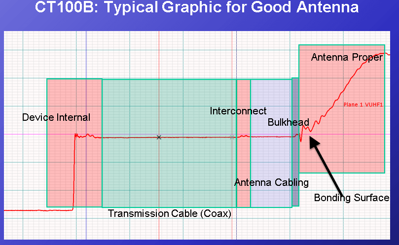
Figure 1: Test 1 Reference. Typical Antenna installation.
Test 2: Identify Bad Engine Harness (incorrect cable impedance)
Procedure:
- Discharge static from Harness A (Known Good)
- Select appropriate cabling and adapters for identified cable/termination.
- Connect appropriate cabling to Device under Test (DUT)
- Connect cable and DUT to CT100 TDR
- Press Orange Autofit button on CT100. CT100 will bracket entire cable length
- Create high-resolution waveform of known-good sample
- Press the CT100 ‘Scan’ button
- Discharge static from Harness B (Known bad)
- Connect appropriate cabling to DUT
- Connect cable and DUT to CT100 TDR
- Perform Autofit if needed
- Analyze Waveform differences between live trace (white) and known good trace (red)
- Look for any differences in amplitude between waveforms (impedance irregularities) between connection point and antenna.
- Adjust cursors and scale as necessary to analyze waveform at higher gain.
- Move active cursor to fault location and notify judge
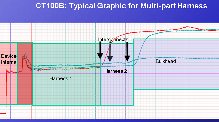
Figure 2: Test 2 Reference. Multi-part cable harness and interconnects
Test 3: Identify Bad / Loose connector
Procedure:
Judge will identify connector with known intermittent fault.
- Select appropriate cabling and adapters for identified cable/termination.
- Discharge static from identified connector
- Connect appropriate cabling to Device under Test (DUT)
- Connect cable and DUT to CT100 TDR
- Perform Autofit if needed
- Analyze Waveform
- Perform Envelope Plot to start intermittent Fault detection:
- Press the CT100 Blue button until the Main Menu appears.
- Select “Envelope Plot”
- An envelope plot will appear on screen and identify any impedance changes in real-time.
- Reset the Envelope Plot as needed if changes are made to scale or position.
- Physically manipulate the DUT (shake) to locate and quantify intermittent faults. Distance to intermittent fault measurements can be made by moving the active cursor to the regions where major impedance changes occur.
- Move active cursor to fault location and notify judge
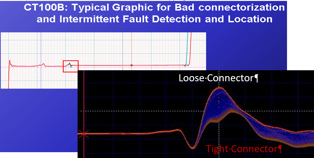
Figure 3: Test 3 Reference. Envelope Plot showing Pass/Fail impedances for 50ohm coaxial interconnect
|